
Training Links
-
How To
-
Lessons Learned
-
Opportunities
-
Training Information
Amateur Radio Classes

References
RF Calculator courtesy Parker Radio Club https://parkerradio.org/toolbox/rfcalc/
Click on "rfcalc" on upper left of the page
HF Propagation Predictions
Antenna Projects
TAPE MEASURE BEAM OPTIMIZED FOR RADIO DIRECTION FINDING
Joe Leggio WB2HOL
Description
This antenna evolved during my search for a beam with a really great front-to-back ratio to use in hidden transmitter hunts. This design exhibits a very clean pattern and is perfect for RDF use. It trades a bit of forward gain in exchange for a very deep notch in the pattern toward the rear. (You could optimize the design for more forward gain, but at the expense of a really good notch in the pattern toward the rear.) It is a design that can be constructed using only simple hand tools (no machine shop needed) and still perform well. It has been duplicated several dozen times by other local hams and has been successfully used as a club construction project.
When I designed this antenna I had one basic idea in mind. It had to be easy to get in and out of the car when hunting for a hidden transmitter. This would be accomplished by the use of steel "tape measure" elements. These elements could fold easily when fitting the antenna into my car and yet still be self supporting. I decided to use three elements to keep the boom from getting too long.
Another of my design goals was to use materials that were easy to obtain. I chose to use Schedule-40 PVC pipe and fittings available at my local hardware store for the boom and element supports. These kept the cost for the antenna very low. The element supports consist of PVC crosses and tees.
Since I had never seen any plans for an antenna using elements made from 1 inch wide steel "tape measure," I had to do the design myself. To assist in the design I used a shareware computer aided yagi design program written by Paul McMahon VK3DIP. It allowed me to optimize the antenna for the cleanest pattern combined with the best front-to-back ratio.
| Performance Predicted by YAGI-CAD | |
| GAIN | |
| Front-to-Back Ratio | |
| 3 db Beamwidth | |
| 3 db Beamwidth | |
When I first built this beam I found it needed a matching network of some kind to have a low SWR. My first attempt was a Gamma match. This was unwieldy. The driven element could barely handle the weight and the Gamma match itself was not very flexible. The best matching network turned out to be a "hairpin match." This is simply a 5 inch length of wire that is connected across the feed points of the driven element. The antenna has some capacitive reactance without the matching network. The 5 inch length of wire has just enough inductance to cancel the capacitive reactance. This resulted in a better match than anything else I had tried.
The wire I used for the hairpin match was enamel insulated 18 gauge solid. Other hams who have duplicated this beam have used just about anything they had on hand. 14 gauge house wire works well, so does a length of 22 gauge hookup wire. It does not seem to matter if it is stranded or solid, use whatever you have available. This results in a very good match across the two meter band once you have adjusted the distance between the halves of the driven element for minimum SWR. (1 inch apart on my prototype).
I used a pair of shears to cut the tape measure elements to length. An old pair of scissors will probably do as well. No matter how you cut the elements be very careful. Those edges are very sharp and will inflict a nasty cut if you are careless. Use some sandpaper to remove the really sharp edges and burrs resulting from cutting the elements to size. I put some vinyl electrical tape on the ends of the elements to protect myself from getting cut. I encourage you to do the same. It will probably be best if you round the corners of the elements once you cut them. Wear safety glasses while cutting the elements. Those bits of tape measure can be hazardous.
The RG58 coax feedline is connected directly to the driven element. No matter what method you use to attach the feedline, make sure you scrape or sand the paint off the tape measure element where the feedline is attached. Most tape measures have a very durable paint finish designed to stand up to heavy use. You do not want the paint to insulate your feedline connection.
If you are careful, It is possible to solder the feedline to the element halves. Care must be taken since the steel tape measure does not solder easily and since the PVC supports are easily melted. You might want to tin the tape measure elements before mounting them to the PVC cross.
If you decide not to solder to the tape measure elements, there are two other methods that have been used to attach the feedline. One method employs ring terminals on the end of the feedline. The ring terminals are then secured under self tapping screws which hold the driven element halves. This method does not allow you to tune the antenna by moving the halves of the driven element. 6-32 bolts and nuts could be used if holes are drilled in the elements near the ends. If the bolt heads are placed nearest the PVC fitting, you could secure ring-terminals with nuts and lock washers. Another possibility is to simply slide the ends of the feedline under the driven element hose clamps and tighten the clamps to hold the ends of the coax. I know this is low-tech, but it works just fine.
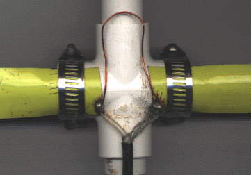 Stainless steel hose clamps are used to attach the driven element halves to the PVC cross which acts as its support. This has the added benefit of allowing you to fine tune your antenna for lowest SWR simply by loosening the hose clamps and sliding the halves of the driven element either closer or further apart. By using the dimensions specified, I found that the SWR was 1:1 at 146.565 Mhz (our Fox-Hunt frequency) when the two elements were spaced approximately 1 inch apart. Figure 1 shows the method used to attach the driven element to the PVC cross.
I used 1 1/2 inch hose clamps to attach all the elements on my prototype beam. Others who have duplicated my design have used self tapping screws to attach the elements to the PVC crosses and tees. Performance is the same using either method. The screws are much less expensive but they do not hold the elements as securely. If you do not use 1/2 inch PVC fittings but instead use 3/4 inch, make sure the hose clamps you buy are large enough to fit.
If you wish a slightly neater looking beam, use the self tapping screws. If you do not mind spending a few more dollars for the hose clamps, use them instead. If I were to build another beam I would use screws for the director and reflector, and hose clamps for the driven element. That would give me the best of both methods.
Rubber faucet washers have been used by some builders between the tape measure element and the PVC fittings on the director and reflector. These allow for the tape to fit the contour of the PVC fitting and will make the antenna look better. Now you know what to do with those washers left over from the assortment you once purchased; You know the ones I mean, the washers that do not fit the faucets you have in your house. If you are an apartment dweller, ask around, these things are stashed in almost every homeowners basement or garage.
Construction:
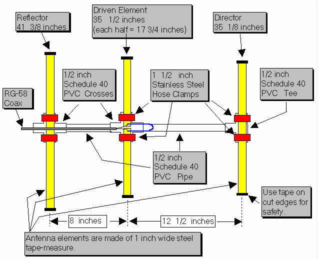
Cut a length of tape measure to 41 3/8 inches. It will be the Reflector element. Cut two lengths of tape measure to 17 3/4 inches. These will be used for the Driven element. Cut one length of tape measure to 35 1/8 inches. It will be used for the Director. Once you have cut the tape measure to length, put vinyl tape on the cut ends to protect yourself from the sharp edges. You will want to scrape or sand off the paint from one end of each of the driven element halves so you can make a good electrical connection to the feedline.
If you are planning to solder the feedline to the driven elements it is best to tin the elements first before attaching them to the PVC cross. If you don’t, the PVC will melt as you apply heat to the element. It would be a good idea to also take the time to form the wire used for the hairpin match into a “U” shape with the two legs of the “U” about 3/4 inch apart. Tin the ends of the hairpin if you plan on soldering it to the driven element. If you tin 1/4 inch of each end of the hairpin it will leave 4 1/2 inches to shape into the “U”.
You will need to cut two lengths of PVC pipe to use as the boom. One should be cut to 11 1/2 inches. It is used to form the boom between the Director and the driven element. The other piece of PVC should be cut to 7 inches. It will be used between the Reflector and the Driven element. Just about any saw will cut through the soft PVC pipe. I used a hacksaw. When we mass produced this antenna as a club project, we marked the pipe and used a portable jig saw to cut the lengths in assembly line fashion. It took longer to measure the pipe than to actually make the cuts. Since the pipe is available in ten foot lengths, you can make a few beams from a single 10 foot length. In any case, you might want to cut a few extras lengths for your friends. They will want to duplicate this once they see your completed antenna.
At this time you can pre-assemble the PVC boom, crosses and tee which will support the tape measure elements. I did not use any cement or glue when I assembled mine. The PVC pipe is secured in the fittings with a friction fit.
The hose clamps I used are stainless steel and have a worm-drive screw which is used to tighten them. They are about 1/2 inch wide and are adjustable from 11/16 inch to 1 1/2 inch diameter. Attach the tape measure elements to the PVC fittings as shown in the accompanying drawing. It is normal for the Reflector and Director elements to buckle a bit as it is tightened to the PVC Tee and Cross. You can eliminate this buckle if you use the washers and self tapping screws to attach these elements instead of the hose clamps. I do not think the beam will withstand as rough a treatment as when hose clamps are used.
How does it perform?
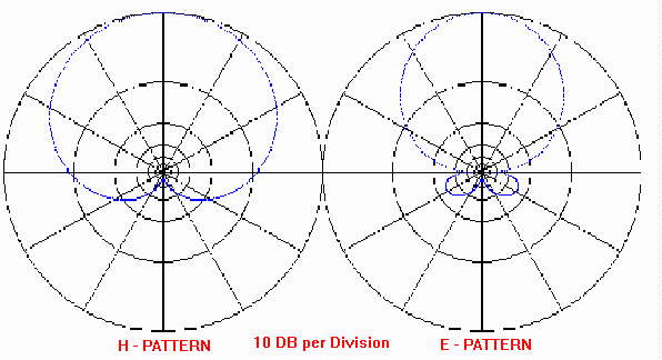
Once you have completed your beam you probably will be interested to see if it performs as well as the computer predicted. The SWR should be less than 2:1 across the entire two meter band. The front-to-back ratio is predicted to be very good with the antenna exhibiting a very deep notch in its pattern towards the rear. The YagiCad 4.1 program produced these antenna pattern graphs showing the pattern you should expect. If you would like to experiment a bit with this program, the yagi specification file for this tape measure beam is available for download here. Simply download the YAGI-CAD program and put the tape measure beam design file in the same directory. You will then be able to experiment with the design.
Note: under Windows95, only the first .yag file will show in the OPEN-FILE menu. You can either move all the other .yag files to a sub-directory or re-start the computer in MS-DOS mode. It works fine there. (I really do not know why this occurs but will blame Microsoft)
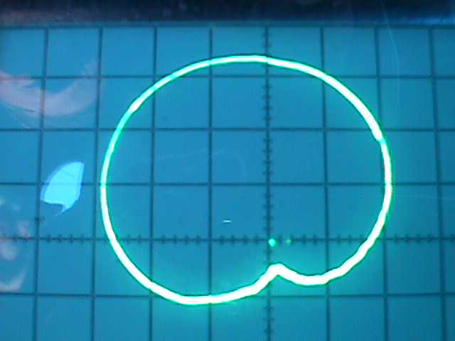
How does the tape measure beam "measure up?"
WB4SUV and WA6EZV used a storage scope connected to a copy of this antenna constructed by KC8FQY and provided the following picture of the actual antenna pattern. I am very happy to see that the computer prediction of a clean pattern with a really great front-to-back ratio was accurate. What do you think?
Summary
This beam has been used on Fox-Hunts, on mountain tops, at local public service events, outdoors, indoors in attics, just about everywhere. The SWR is typically very close to 1:1 once adjusted. Front to back performance is exactly as predicted. The null in the rear of the pattern is perfect for transmitter hunts. When tested using a sensitive field strength meter and a low powered fox transmitter, full scale readings were seen from a distance of ten feet. With the same field strength meter I was able to point the antenna away from the transmitter and move the reflector element to within a few inches of the transmitter antenna and still not see a reading. I don’t have the facilities to verify a 50 db notch as predicted by the Yagi-Cad software but It sure seems close. The flexible elements have taken a lot of abuse. My antenna has seen a lot of use and has held up quite well. Best of all, when on a fox-hunt, this beam is a breeze to get in or out of the car.
Copyright 1993 - Joseph Leggio - all rights reserved.
Powerpole General Assembly Instructions
Here is a link to a YouTube video
and below is the detail.
=====================================================================================
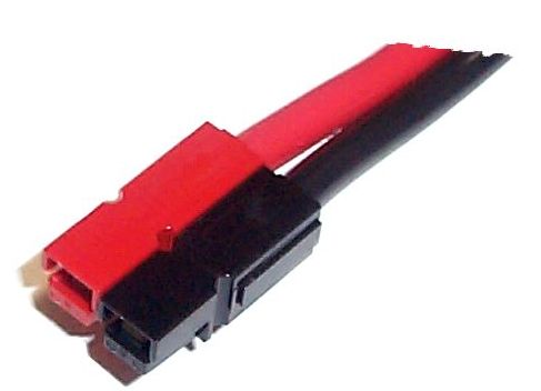
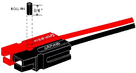
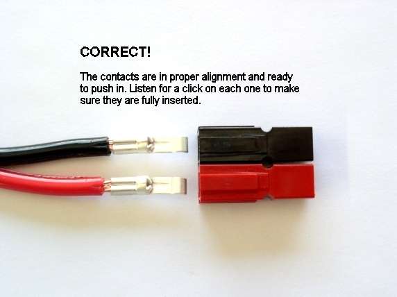
Assemble the red and black plastic housings together correctly on the first try, they fit snugly and can be difficult to get apart. See the picture below for ARES /RACES standard orientation. Note that you can assemble the red and black insulated housings in other ways for special applications.
Put the connector housings together before putting the connector pins in, this is easier, especially when using heavy paired wire.
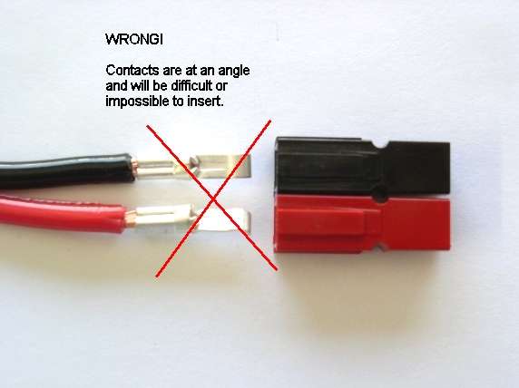
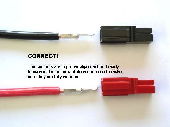
Before soldering or crimping the contacts on to heavy paired wire, orient the contacts so that they are both facing the correct direction so that they go in the housings without twisting the wire.
The plastic housings are held together with dovetail joints. Always slide these joints together! They will be damaged if you try to snap them together or apart. They ONLY slide together in one direction. This should be obvious by looking at them carefully.
Powerwerx recommends the use of slotted retaining pins. Others do not like the possibility of them falling out in service. If your application is critical and that you want to make the pairing permanent you can use a cyanocrylic glue (Crazy Glue) to hold the connector bodies together.
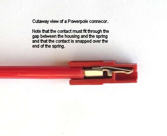
The contacts go in the housings in only one way. Insert the contacts with their sharp edge down against the flat spring that is in the housing. They should slide in and click. If you do not hear a click or they are not fully seated, fix them. When they are inserted fully you should notice that the contact and it's wire "floats" slightly inside it's housing. When looking in from the front of the housing the contact tip should slide over the top of the internal hosing spring. This is the clicking sound that you hear.
Be careful when crimping. You may make the contact out of round and it will not slide into the contact easily. This may occur with different types of crimpers and various gauges of wire. To fix this situation you may have to rotate the contact 90 degrees from the original crimping orientation and re-crimp either with the original crimper or a pair of pliers. In any case you need to make the barrel of the contact round again so it can slide in the housing.
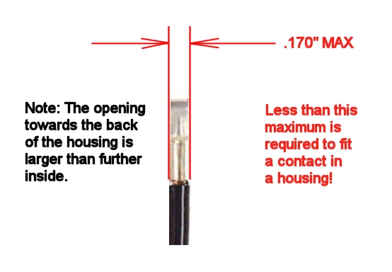
YOU WILL NOT BE ABLE TO INSERT THE CONTACTS INTO THE HOUSINGS IF THEY ARE TOO WIDE AFTER SOLDERING OR CRIMPING!
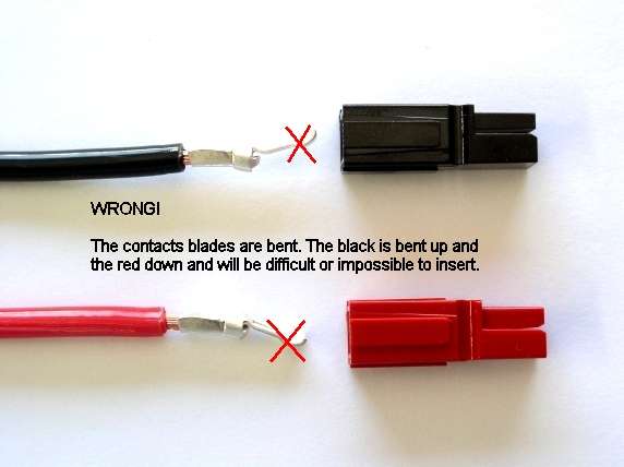
Tug slightly on the assembled connector to make sure the contacts are locked in place. If you have trouble getting the contact to lock in to the housing you may have squashed the contact wider deformed it some how. Look at the side profile of the contacts before and after crimping, you may have to bend it back straight before inserting it in to the housing.
When soldering the contact pins, be careful not to use too much solder. Keep the solder inside, where the wire goes. If a blob of solder gets on the outside of the connector body you may have trouble putting the contact into the housing. If you get solder on the contact surface area you will not make a good contact.
When crimping the contact pins use a crimp that contains the wire completely inside the pin and doesn't spread the connector apart. A good crimp is one where the dimensions of the crimped portion are no more than an un-crimped pin. If the crimp is flattened out you will not be able to easily push the pin in to the body. If you bend the contact blade in relation to the crimp area you should straighten it before putting it in to the body.
It is possibly to use larger or smaller gauge wire with the 30 and 45 amp connectors. The 30 amp contacts will work with difficulty with #10 wire if you cut the end cleanly and carefully put each and every strand of that wire in to the pin. It may be is easier to use 45 amp connectors on #10 wire. Using 16 gauge or smaller wire in a 30 amp contact requires that you double or triple up the wire to fill the crimp receptacle of the contact to get a good crimp.
A properly crimped contact should have a minimum hold on the wire of more than 25 pounds. A pair of connectors should snap together with 6 to 8 pounds force.
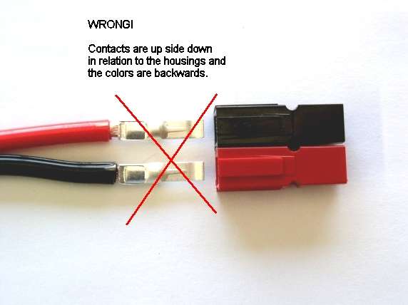
Last but not least, MAKE SURE you have the polarity correct before plugging in you equipment. "Measure twice, cut once" as the saying goes.
Read more: Anderson Powerpole® Assembly Instructions - Powerwerx